4 Coordinate reference systems
Each spatial data has a defined location in space which is most often input through coordinates. Coordinates in some spatial reference system (SRS) or coordinate reference system (CRS) are on a sphere or ellipsoid, or in a projection.
4.1 Geographic coordinate reference system
The geographic coordinate reference system is a geometric model which defines:
The model of Earth’s shape (e.g., ellipsoid with parameters
aande, large axis and first numerical eccentricity);The prime meridian (usually the Greenwich meridian by default);
Geodetic datum.
Coordinates on the geographic coordinate reference system are usually curvilinear (or ellipsoidal rectangular), geodetic length (\((\lambda)\) longitude) and geodetic width ((\(\mathrm{\phi}\)) latitude); additionally height h can also be given, Figure 4.1.
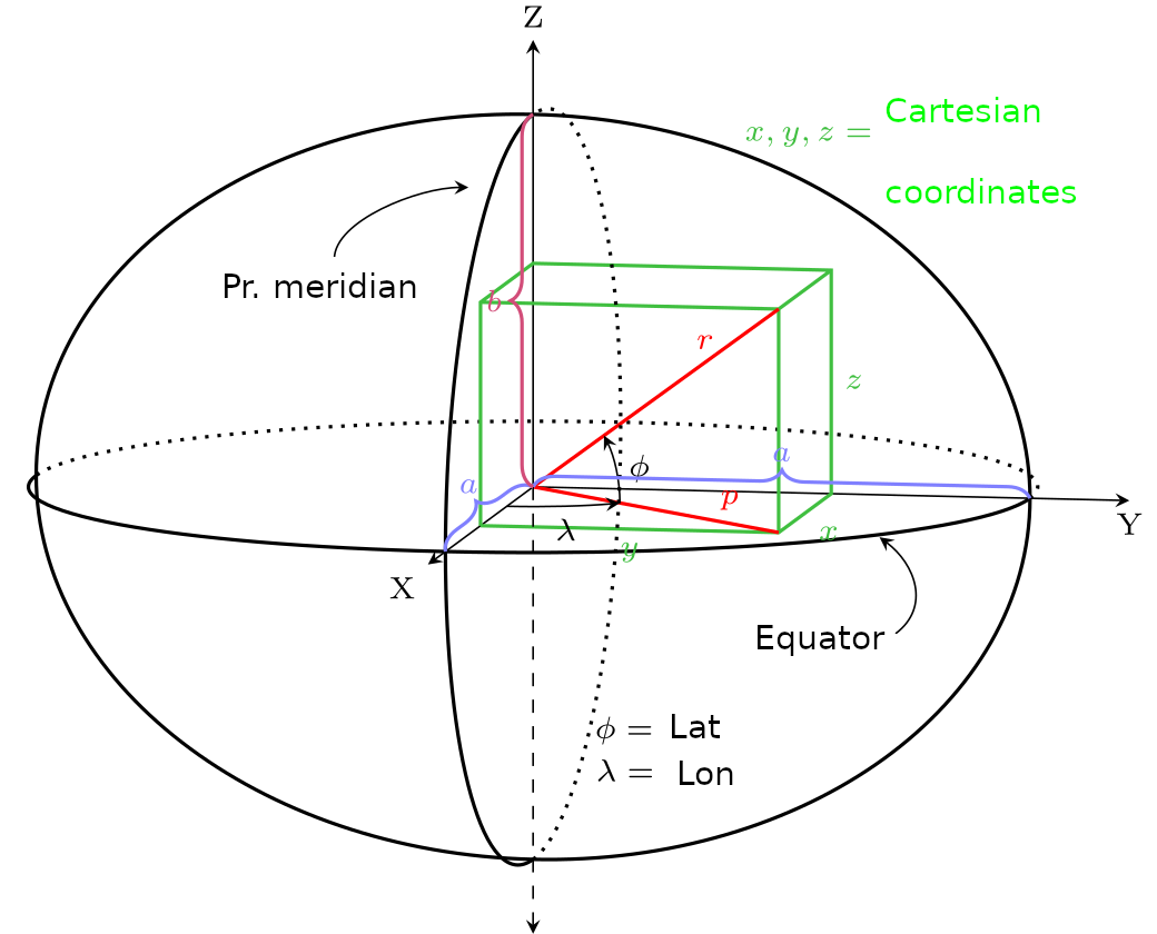
Figure 4.1: Curvilinear coordinates for a point: geodetic length (\(*λ*\)) and geodetic width (\(*φ*\)). Coordinates are given on an ellipsoid with parameters a for the large semiaxis and b for the small semiaxis. Rectangular ellipsoid coordinates are marked in green. (Adapted from Krishnavedal (Own work) CC BY-SA 3.0)
Geodetic width (latitude) is the angle between the normal on the ellipsoid in the observed point and the equatorial plane. The geodetic length (longitude) is the angle between the meridian of the observed point and the prime meridian, usually taken to be the Greenwich meridian.
The ellipsoid used to approximate Earth’s shape is a bi-axial ellipsoid, defined by two linearly independent parameters, e.g., by the large and small semiaxis (a, b), by the large axis and flattening (a, f), or by the large axis and first numerical eccentricity (a, e). Some parameters are given in Table 4.1.
| Parameter | Description |
|---|---|
| a | Large semiaxis |
| f = (a-b)/a | Flattening |
| b = a- fa | Small semiaxis |
| e2 = 2f -f 2 | First numerical eccentricity |
| e’ 2 = (2f - f 2)(1 - f )–2 | Second numerical eccentricity |
The transformation of geodetic coordinates φ, λ, and h into rectangular geocentric coordinates X, Y, and Z can be performed using the following expressions (Heiskanen i Moritz 1967):
\[ X=(N+h) cos φ cosλ \] , \[ Y=(N+h) cos φ sin λ \] , \[ Z=[(1 – e^2) N + h] sin φ \]
where N is the curvature radius in the transverse ellipse.
\[ N = a (1 – e^2 sin^2 φ)^{–1/2} \].
In order to know the precise location of some point in space, besides its coordinates on an ellipsoid, other system parameters need to be known as well, such as the shape of the ellipsoid and the geodetic datum. The geodetic datum is a set of constants defining the position of the reference ellipsoid relative to Earth. The datum can be defined in two ways, as a topocentric or geocentric datum.
A geocentric datum is defined by seven parameters in the following manner:
Three parameters define the position of the reference ellipsoid relative to Earth’s center - \((\Delta X,\ \text{ΔY},\ \text{ΔZ}\)) (ili tx, ty, tz);
Three parameters define the orientation of the reference ellipsoid - \((\alpha,\ \beta,\ \gamma)\);
One scaling parameter - \((\mu\ (\text{ili}\ \mu=1+s))\); parameter \(s\) is usually in ppm.
Figure 4.2 shows the relationship between the local, non-geocentric, reference ellipsoid and the global ellipsoid. The global geocentric ellipsoid is optimal for approximating the entire surface of the Earth (geoid).
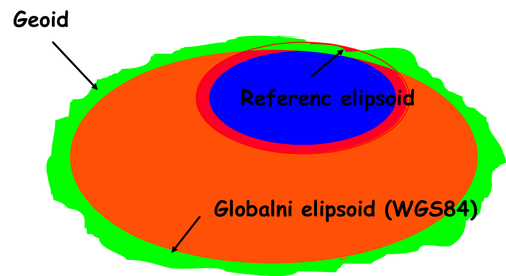
Figure 4.2: Relationship between the geoid, i.e., global ellipsoid, and the reference, i.e., local, ellipsoid; the relationship is not to scale.
WGS84 is a conventional terrestrial reference system with an associated global ellipsoid WGS84 approximating the geoid’s entire surface. The ellipsoid’s center of mass matches the Earth’s, and its axes match the conventional Earth’s axes. Hence, seven datum parameters are defined with information on how much the reference ellipsoid is translated and rotated by each axis relative to WGS84, and on the ratio of lengths on the WGS84 and reference ellipsoids. The reference (local) ellipsoid is chosen to best approximate a part of the Earth’s surface.
Using a three-dimensional Helmert transformation, coordinates can be converted from the local to the global ellipsoid, and vice versa. The set of rectangular geocentric Cartesian coordinates XWGS84¸ YWGS84, ZWGS84 can be transformed into a set of non-geocentric Cartesian coordinates XBessel¸ YBessel, ZBessel using an equation, in this case on a Bessel ellipsoid, with a Hermannskogel datum (old Serbian state coordinate system), Figure 4.3.
\[ \begin{bmatrix} X^{Besel} \\ Y^{Besel} \\ Z^{Besel} \end{bmatrix} = \begin{bmatrix} t_x \\ t_y \\ t_z \end{bmatrix} + (1 + s\times10^{-6}) \cdot \begin{bmatrix} 1&-r_z&r_y \\ r_z&1&-r_x \\ -r_y & r_x & 1 \end{bmatrix} \cdot \begin{bmatrix} X^{WGS84} \\ Y^{WGS84} \\ Z^{WGS84} \end{bmatrix}. \]
,
where
tx, ty, and tz are parameters for translation by corresponding coordinate axes,
s is the scale parameter and
R is the rotation matrix around coordinate axes XWGS84, YWGS84, and ZWGS84.
If the rotation angles α, β, and γ around the coordinate axes XWGS84, YWGS84, and ZWGS84 are small (when converting results from the WGS84 system into the State coordinate system, they are in the order of several arc seconds), then the R matrix can be presented in the following form:
\[ R=\begin{bmatrix} 1&-r_z&r_y \\ r_z&1&-r_x \\ -r_y & r_x & 1 \end{bmatrix} \approx \begin{bmatrix} 1&-\gamma&\beta \\ \gamma&1&-\alpha \\ -\beta & \alpha & 1 \end{bmatrix} . \]
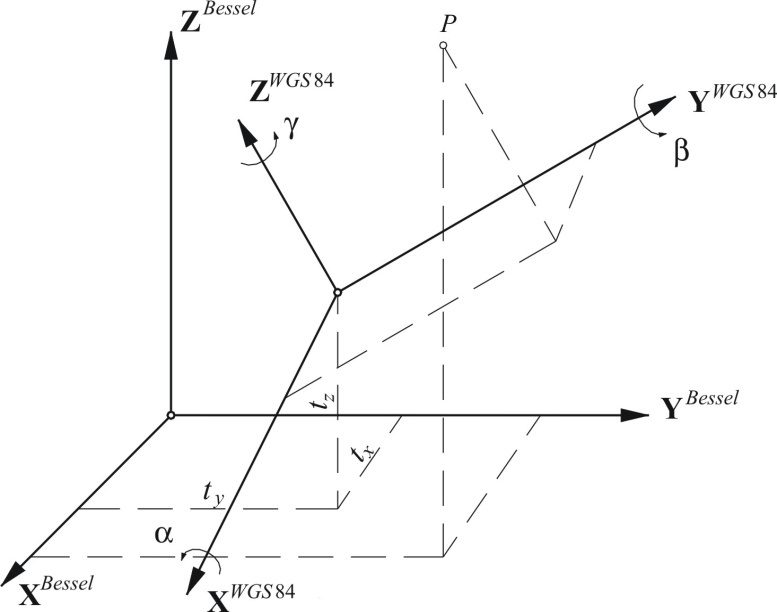
Figure 4.3: Three-dimensional datum transformation
Hence, if the seven datum parameters are known (tx, ty, tz, α, β, γ, and s), the values of coordinates XBessel, YBessel, ZBessel can be calculated based on coordinates XWGS84¸ YWGS84, ZWGS84. \[ \begin{matrix} X^{Bessel} & = & c_x+(1+s\times10^{-6})\cdot (X^{WGS84}-r_z\cdot Y^{WGS84}+r_y\cdot Z^{WGS84})\\ Y^{Bessel} & = & c_y+(1+s\times10^{-6})\cdot (r_z\cdot X^{WGS84}+Y^{WGS84}-r_x\cdot Z^{WGS84})\\ Z^{Bessel} & = & c_z+(1+s\times10^{-6})\cdot (-r_y\cdot X^{WGS84}+r_x\cdot Y^{WGS84}+Z^{WGS84}).\\ \end{matrix} \]
4.2 Coordinate reference systems in projection
Coordinates for spatial data are usually in the form of rectangular coordinates in the map’s plane, with a label (x,y, X,Y, or E,N). Formulas used for converting curvilinear spherical or ellipsoidal (geodetic) coordinates into a map’s plane, represent cartographic projections. Coordinates are then defined in a projected coordinate reference system. When performing cartographic projections, deformations of angles (shapes), lengths, and areas, occurs. Generally, according to the type of deformation, projections are separated into conformal (maintaining fidelity of shapes and angles), equal-area (equivalent, no deformations of areas), and conditional projections. Converting from curvilinear to rectangular coordinates is called a cartographic task and vice versa, converting from rectangular to curvilinear coordinates is called an inverse cartographic task.
For more details on projections, see (Jovanović 1984, Snyder (1987), Canters and Decleir (1989), Bugayevskiy and Snyder (2013)).
A projected coordinate reference system is a geometric model which defines the following:
Projection;
Model of Earth’s shape (e.g., ellipsoid with parameters a and e);
Prime meridian (e.g., Greenwich meridian);
Datum.
Once the projected coordinates are known and the coordinate reference system is defined, it is possible to convert coordinates from one coordinate reference system to another, Figure 4.4.
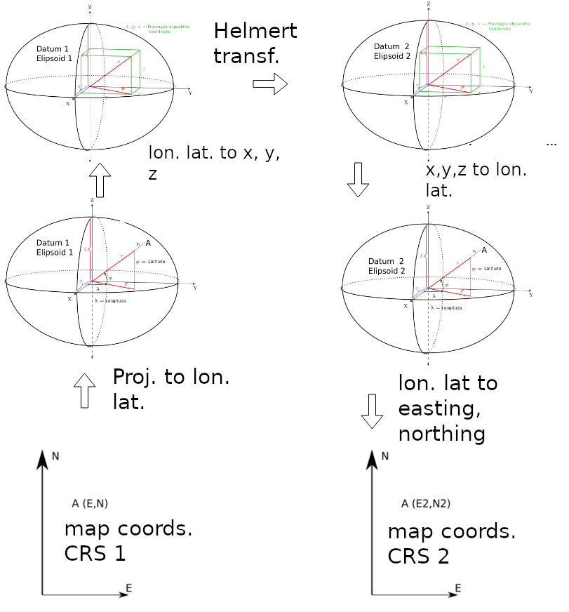
Figure 4.4: Schematic representation of conversion from one coordinate system into another.
References
Jovanović, Velibor. 1984. Matematička Kartografija. VGI.
Snyder, John Parr. 1987. Map Projections–A Working Manual. Vol. 1395. US Government Printing Office.
Canters, Frank, and Hugo Decleir. 1989. The World in Perspective: A Directory of World Map Projections. John Wiley & Sons.
Bugayevskiy, Lev M, and John Snyder. 2013. Map Projections: A Reference Manual. CRC Press.